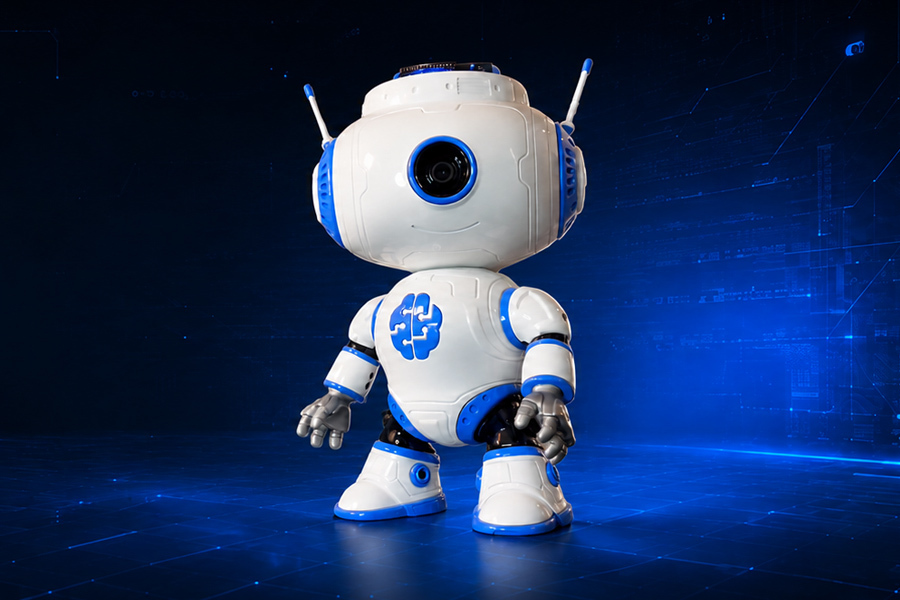
The robot can greet you by moving its arms and head, play sounds, animate its display, sense nearby objects using a distance sensor, and use its camera for computer vision applications running on the Arduino® UNO™ Q.
In this guide, we'll go through the complete build, from understanding the electronics and assembling the 3D-printed parts to programming the display, buzzer, distance sensor, and servos.
How It Works
At the center of JBR-001 is the Arduino® UNO™ Q. It controls the robot's display, sensors, buzzer, and servo motors, while also providing the computing capabilities needed for more advanced applications such as computer vision.
JBR-001 uses three servo motors to create movement. One controls the head, while the other two control the left and right arms.
A distance sensor located at the back of the head allows JBR-001 to detect nearby objects behind it. The buzzer provides simple audio feedback, while the integrated display gives JBR-001 its animated face and heartbeat.
The camera adds another level of interaction, allowing the robot to go beyond simple distance sensing and respond to what it sees.
The three servo motors use an external power supply rather than drawing their power directly from the Arduino® UNO™ Q. The external power supply and the UNO™ Q share a common ground, allowing the control signals from the board to reliably control the servos.
The camera and Arduino® UNO™ Q are connected through a USB-C hub.
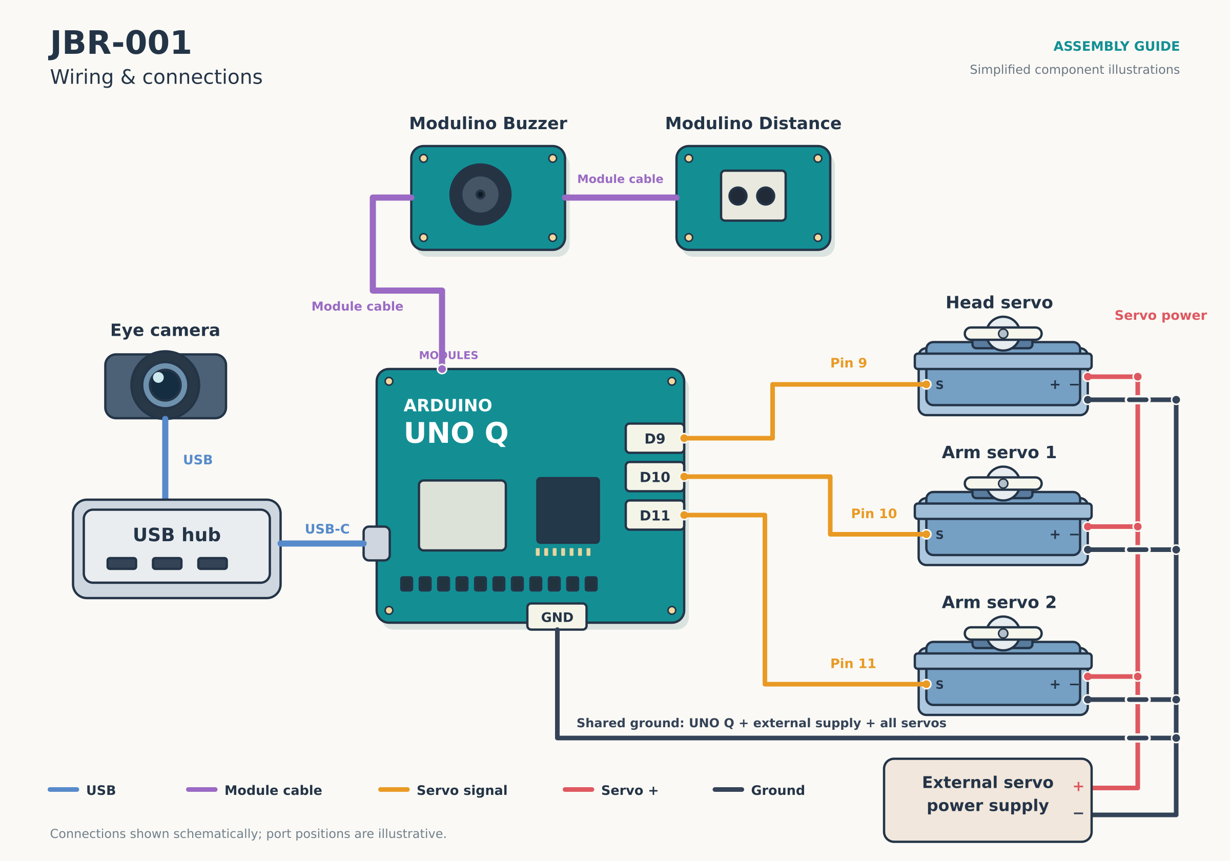
Main wiring connections for the JBR-001 robot
Main connections
Head servo → pin 9
Left arm servo → pin 10
Right arm servo → pin 11
Three servos → external power supply
External power supply ground → Arduino® UNO™ Q ground
Modulino™ Distance → Modulino™ Buzzer
Modulino™ Buzzer → Arduino® UNO™ Q
Arduino® UNO™ Q → USB-C hub
Camera → USB-C hub
Important: Do not power all three servo motors directly from the Arduino® UNO™ Q. Use a suitable external power supply for the servos and connect the grounds of the external supply and UNO™ Q together.
Assembling the JBR-001
One of the goals behind JBR-001 was to make the robot something you could build yourself. The body is made from 3D-printable parts, with the electronics and servos installed directly inside the printed structure.
You will need:
Arduino® UNO™ Q
Camera
Distance sensor
Buzzer
Three servo motors
External power supply for the servos
USB-C hub
JBR-001 3D-printed parts
Cables, screws, and mounting hardware
All 3D-printable STL files for JBR-001 can be found here.
Start by printing the JBR-001 components and assembling the main body. Install the servo motors as you assemble the head and arms so that their shafts align correctly with the moving parts.
The head servo provides horizontal movement, while one servo inside each side of the body controls an arm.
Once the mechanical parts are assembled, install the Arduino® UNO™ Q and route the servo, sensor, camera, and power cables through the body. Keeping the wiring organized at this stage makes closing the robot considerably easier.
The camera is installed in the head, giving it a forward-facing view of the environment.
The distance sensor is positioned so that JBR-001 can detect someone approaching from the back.
For a complete walkthrough of the mechanical assembly, watch the assembly video below, where Goran and Nenad explain it step by step.
Bringing the Head Display to Life
The display is one of the simplest ways to give JBR-001 some personality.
When the robot is idle, it displays a heart that continuously pulses between two sizes. This creates a subtle heartbeat animation and gives the robot a visual indication that it is running even when nothing else is happening.
The animation is created using two small bitmap representations of the heart: a larger heart and a smaller one.
// Small heart
// flipped to match display orientation
uint8_t heartSmall[8][13] = {
  {0,0,0,0,0,0,0,0,0,0,0,0,0},
  {0,0,0,0,0,1,1,1,0,0,0,0,0},
  {0,0,0,0,1,1,1,1,1,0,0,0,0},
  {0,0,0,1,1,1,1,1,1,1,0,0,0},
  {0,0,1,1,1,1,1,1,1,1,1,0,0},
  {0,0,1,1,1,1,0,1,1,1,1,0,0},
  {0,0,0,1,1,0,0,0,1,1,0,0,0},
  {0,0,0,0,0,0,0,0,0,0,0,0,0}
};

// Large heart
// flipped to match display orientation
uint8_t heartLarge[8][13] = {
  {0,0,0,0,1,1,1,1,1,0,0,0,0},
  {0,0,0,1,1,1,1,1,1,1,0,0,0},
  {0,0,1,1,1,1,1,1,1,1,1,0,0},
  {0,1,1,1,1,1,1,1,1,1,1,1,0},
  {1,1,1,1,1,1,1,1,1,1,1,1,1},
  {1,1,1,1,1,1,1,1,1,1,1,1,1},
  {0,1,1,1,1,1,0,1,1,1,1,1,0},
  {0,0,1,1,1,0,0,0,1,1,1,0,0}
};
Rather than stopping the entire program with long delays, the heartbeat can be updated based on elapsed time. This is important because JBR-001 still needs to monitor its distance sensor and respond to other events while the animation is running.
// Heartbeat animation
unsigned long heartbeatTimer = 0;
int heartbeatStep = 0;

void heartbeat() {
  unsigned long now = millis();

  switch (heartbeatStep) {

    case 0:
      matrix.renderBitmap(heartLarge, 8, 13);
      heartbeatTimer = now;
      heartbeatStep = 1;
      break;

    case 1:
      if (now - heartbeatTimer >= 120) {
        matrix.renderBitmap(heartSmall, 8, 13);
        heartbeatTimer = now;
        heartbeatStep = 2;
      }
      break;

    case 2:
      if (now - heartbeatTimer >= 100) {
        matrix.renderBitmap(heartLarge, 8, 13);
        heartbeatTimer = now;
        heartbeatStep = 3;
      }
      break;

    case 3:
      if (now - heartbeatTimer >= 160) {
        matrix.renderBitmap(heartSmall, 8, 13);
        heartbeatTimer = now;
        heartbeatStep = 4;
      }
      break;

    case 4:
      if (now - heartbeatTimer >= 700) {
        heartbeatStep = 0;
      }
      break;
  }
}
The display can easily be adapted for other expressions and states. For example, different graphics could indicate that JBR-001 has detected an object, recognized something with its camera, or is waiting for an interaction.
Adding Sound with the Buzzer
JBR-001 uses a buzzer to provide simple audio feedback. For example, when the robot detects someone nearby, it can play a short sequence of notes as a friendly greeting.
A simple greeting can be created with just four tones:
// Play JBR-001's friendly greeting
void playHello() {
  buzzer.tone(523, 120);   // C5
  delay(150);

  buzzer.tone(659, 120);   // E5
  delay(150);

  buzzer.tone(784, 180);   // G5
  delay(210);

  buzzer.tone(1047, 250);  // C6
  delay(270);
}
The ascending sequence gives JBR-001 a short and recognizable "hello" sound without requiring a speaker or audio files.
Sound can also be used to communicate different robot states. Different tone sequences could indicate successful detection, warnings, startup, or other events in your own applications.
Sensing Nearby Objects
JBR-001 uses a distance sensor located at the back of its head to sense nearby objects and measure how far away they are. The sensor continuously measures the distance behind the robot and makes this information available to your application.
Reading the distance sensor is straightforward. You can define a distance threshold and use it to trigger actions such as moving the head or arms, playing a sound, or changing the display animation.
This gives you another simple input for creating interactive behaviours and combining physical sensing with JBR-001's other capabilities.
// React when someone approaches
if (distanceSensor.available()) {
  float distance = distanceSensor.get();

  if (distance < DETECTION_DISTANCE && !objectDetected) {
    objectDetected = true;
    playHello();
  }

  // Ready for the next greeting once they move away
  if (distance > RESET_DISTANCE) {
    objectDetected = false;
  }
}
Controlling the Servos
Movement is provided by three servo motors. The head servo is connected to pin 9, while the two arm servos are connected to pins 10 and 11.
Each servo can be controlled by specifying its target angle:
headServo.write(90);From there, we can create more natural movement by moving between several positions rather than immediately jumping between large angles.
For example, JBR-001 can turn its head slightly toward a visitor while raising and lowering its arms as part of the greeting animation.
The servo motors require more current than should be supplied directly by the Arduino® UNO™ Q, especially when several motors move at the same time. For this reason, all three servos are powered from an external power source.
The ground of the external servo power supply must also be connected to the ground of the Arduino® UNO™ Q. Without this common electrical reference, the control signals sent from the UNO™ Q to the servos may not work reliably.
When creating your own animations, keep the mechanical limits of the robot in mind. Servo movement should remain within the range supported by the printed joints rather than automatically using the servo's entire theoretical 0° to 180° range.
Small movements often work better for JBR-001. A slight head turn or short arm movement can make the robot expressive without making the animation feel overly mechanical.
Adding Computer Vision
The camera is where JBR-001 starts becoming much more than a sensor-controlled desktop robot.
Connected to the Arduino® UNO™ Q through the USB-C hub, the camera can provide images for computer vision applications running on the robot.
This opens up many possibilities. JBR-001 could recognize objects placed in front of it, react differently depending on what it sees, detect specific items, or combine visual information with its distance sensor to create more sophisticated interactions.
For example, instead of simply knowing that something is standing in front of the robot, computer vision can help JBR-001 understand what it is looking at.
That is also where synthetic data becomes particularly useful. We can use images for specific objects and scenarios, train a computer vision model, and deploy it to JBR-001 without first having to manually capture and label large numbers of images.
Conclusion
You now have the foundation of a working JBR-001.
We started with a set of 3D-printed parts and an Arduino® UNO™ Q and turned them into a desktop robot that can display animations, detect distance of objects, make sounds, and move its head and arms.
JBR-001 is open source so that you can modify it, experiment with it, and make it your own. You can create new display animations, design different sounds and movements, add sensors, modify the 3D-printed parts, or completely change how the robot behaves.
And with the camera and computing capabilities of the Arduino® UNO™ Q, you can also start building interactions based on what the robot sees.